Search

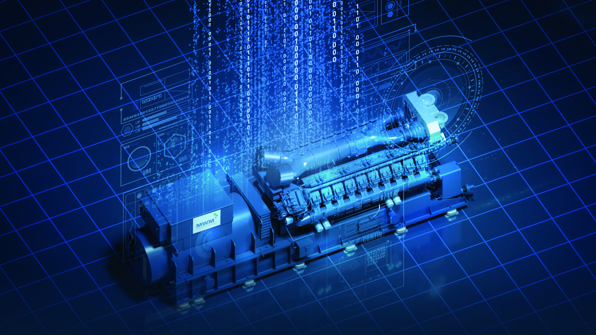
A genset, otherwise known as a generating set, includes a prime mover (the engine) and an alternator to produce electrical power at high efficiency.
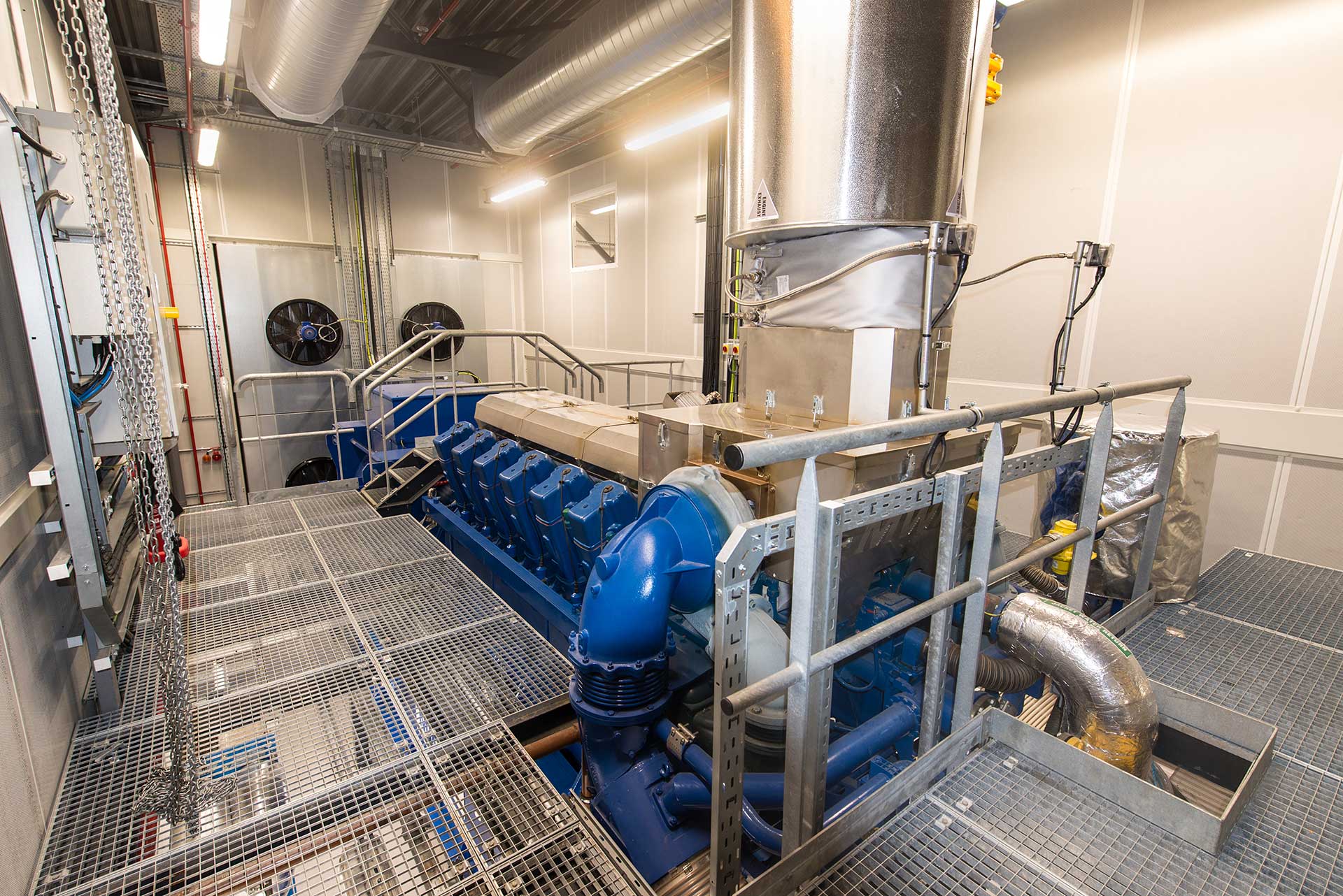
MWM gensets can be configured to produce high efficiency electrical power only. The engine, alternator and other supporting equipment is located on a skid. Waste heat from the engine is dissipated and lost to atmosphere in the exhaust gas and via the engine cooling circuit linked to heat dump radiators.
Gensets are commonly used whereby the site has no local heat requirements and where there is no demand for a Combined Heat and Power (CHP) configuration.
Typical applications for gensets include flexible generation or peaking stations, whereby the genset produces electrical power to support and balance the grid during periods of high electrical demand and low supply from renewable technologies.
Finally, the generating set is controlled by proprietary and sophisticated control panel management system allowing engineers to communicate, interface, analyse, diagnose, and control the plant to ensure optimal performance and availability of the genset.

Local or Remote Operation
Fuel Flexible
Hydrogen-Ready
Energy Resilience
High Efficiency
Fuel Efficiency
Scalable Design
Modular Power Plant
Hybrid Power Solution
A reciprocating engine (also known as a piston engine) is a machine with reciprocating pistons. The generating set converts thermal energy from the combustion of air and fuel into mechanical work, in this case a crankshaft.
Mechanics of the engine is to move a crankshaft connected to a piston cylinder mechanism by creating large pressure inside the engine’s cylinders.
The MWM engine is connected to an electrical generator (alternator) by a drive coupling to produce electricity.
The engine generator is connected to an electrical circuit breaker so the genset can be connected to the site electrical circuit via an electrical cable. The circuit breaker will synchronise the gas engine to the mains so it can operate in parallel to the existing grid supply.
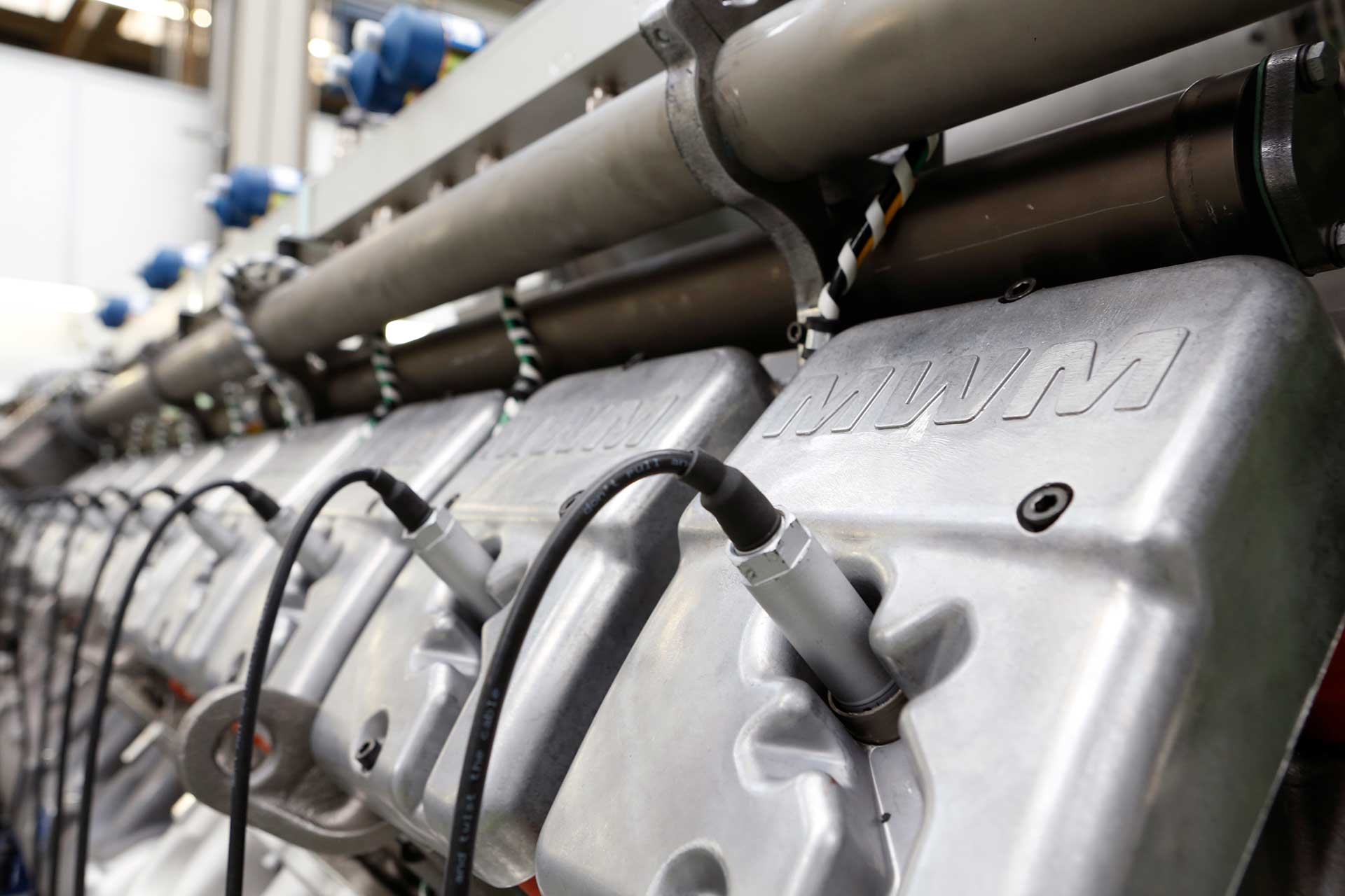
MWM generating sets are spark ignited and operated in a 4-Stroke process:
Stage 1: Intake Stroke
The intake valve is open, and the air-fuel mixture is drawn into the combustion chamber via the downward movement of the piston. The exhaust valve is closed.
Stage 2: Compression Stroke
With both intake and exhaust valves closed, the upward movement of the piston causes the air-fuel mixture to be compressed towards the spark plug. The compression makes the air-fuel combination volatile for easier ignition.
Stage 3: Power Stroke
During the combustion stroke, both intake and exhaust valves remains closed, and the spark plug produces a spark to ignite the compressed air-fuel mixture. The combustion produces mechanical energy which drives the piston downwards to turn the crankshaft.
Stage 4: Exhaust Stroke
The final cycle is the exhaust stroke in which the exhaust valves open and the exhaust gases are expelled by the returning piston.
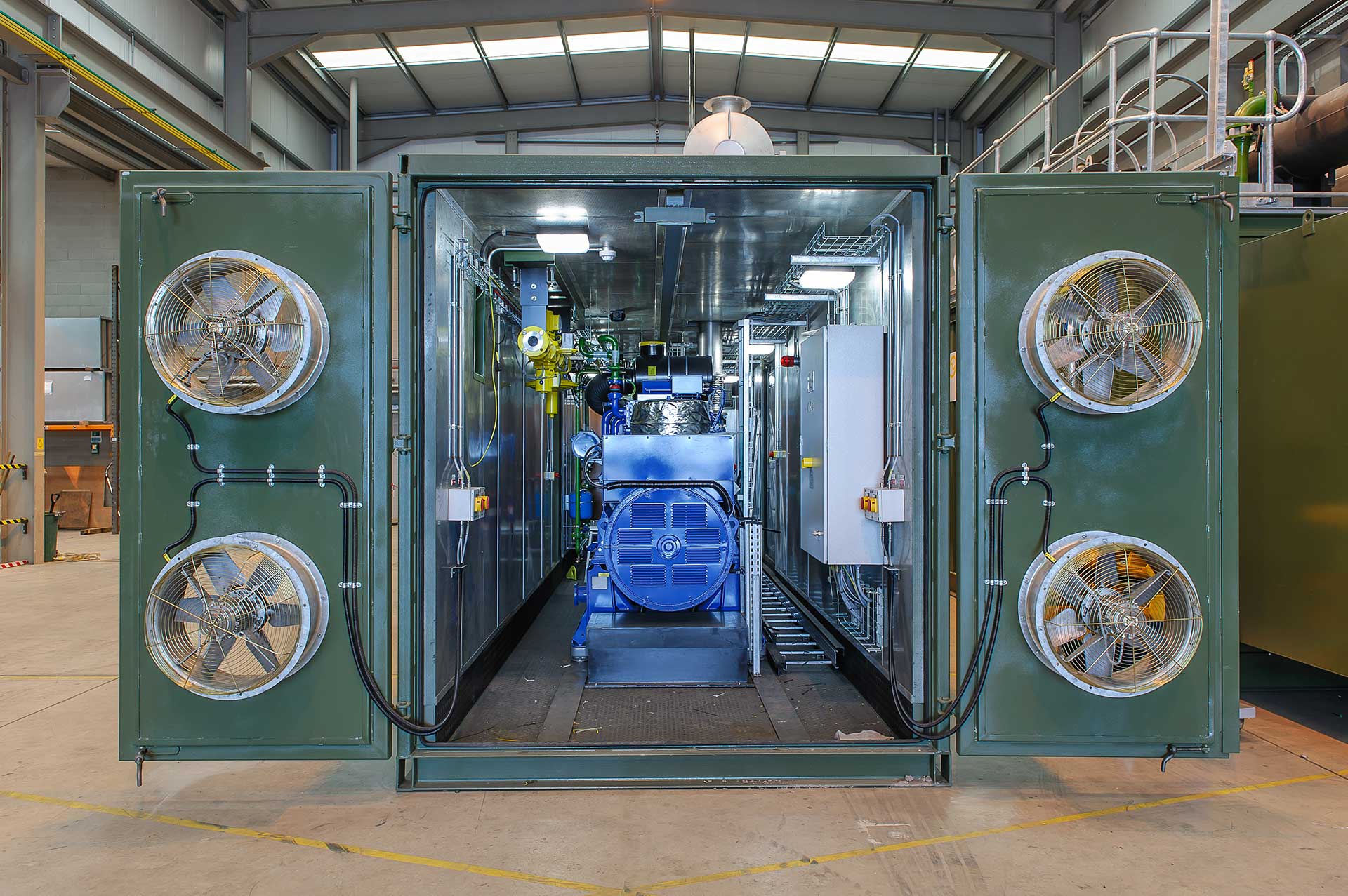
MWM gas engines can be housed within containerised enclosures and configured for various operational scenarios.

A high-quality engineered module which can be deployed where economical and expedited installation is required and is suitable for modular ‘plug and play’ applications.
Read more
MWM gas engines can be configured for Island Mode and can operate independently of any national or local power distribution network. Find out more.
Read more
Gas engines configured for Black Start operation can restore power at site in the event of a system outage.
Read more


Copyright © Edina. All Rights Reserved.